Week1
Computer-Aided DesignDesigning ‘Printed Circuit Box’, not a ‘Printed Circuit Board’
One side had to be open for xiao board access, and other three work as capacitive sensing pads. One work as base connection for xiao, and also routes for capacitive sensing are there. The last panel consist of 10 LEDs, which are percievable from the both sides of the glass.
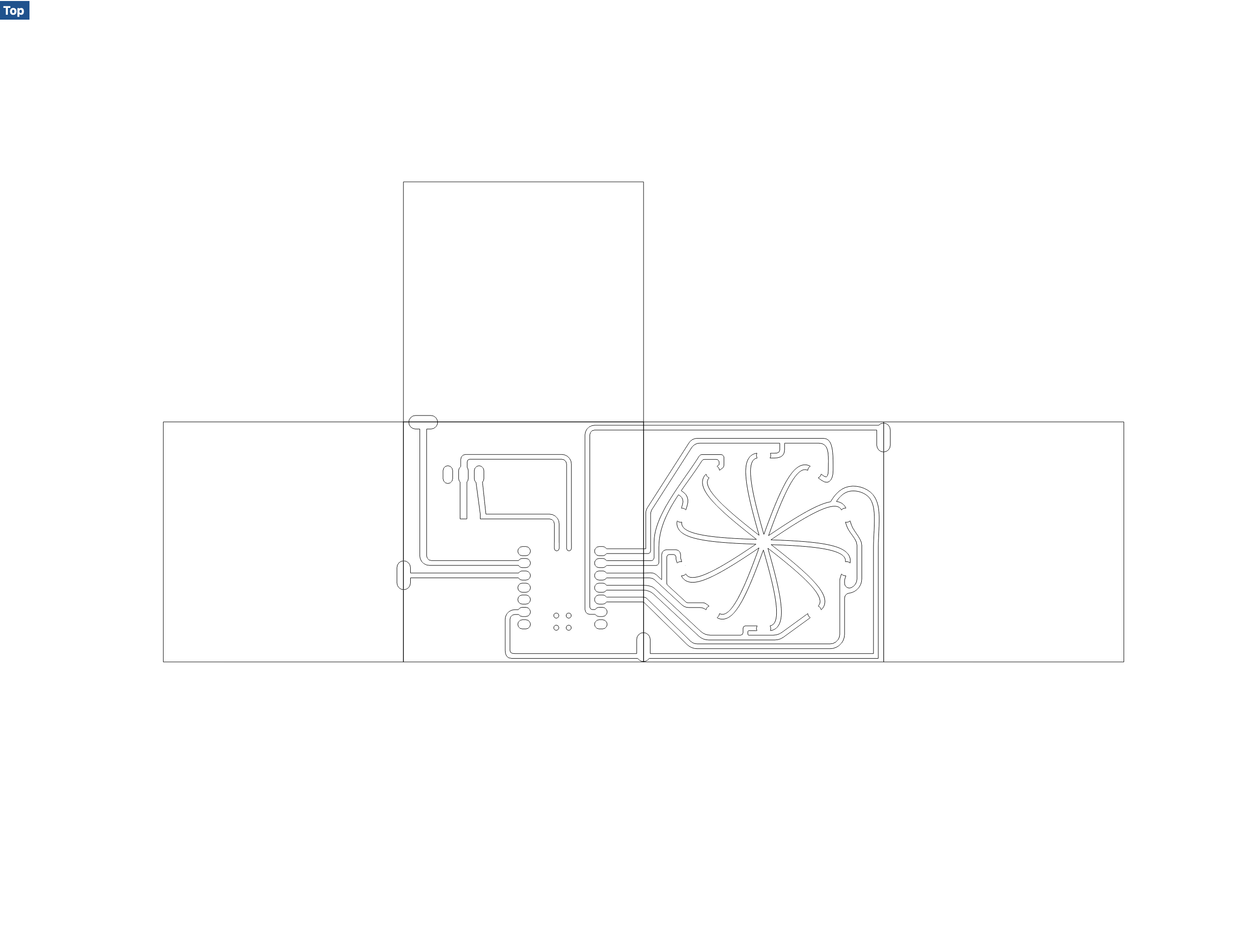
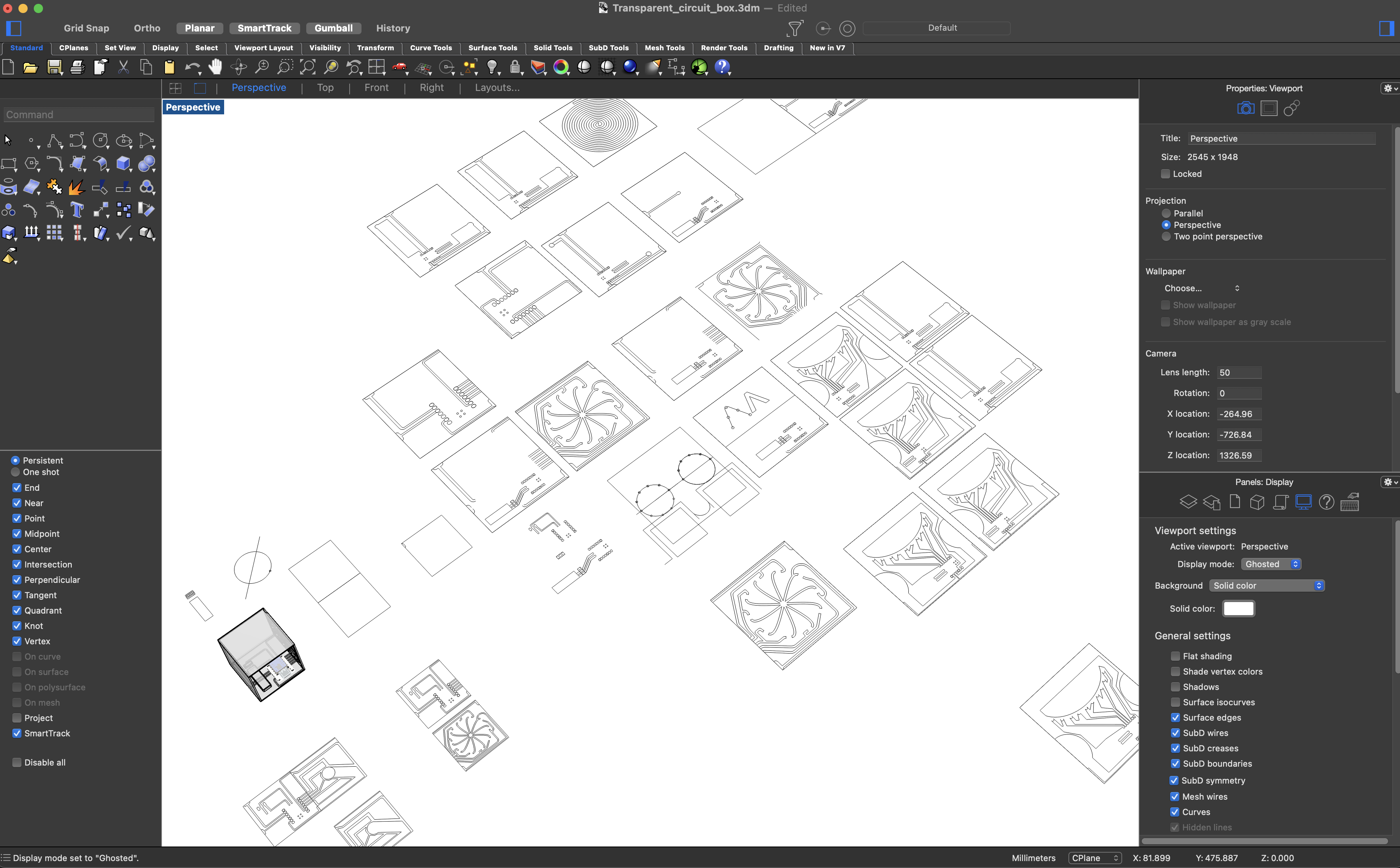
2D Flat layout - Does it look too decorative? They will be clear so it doesn’t matter.
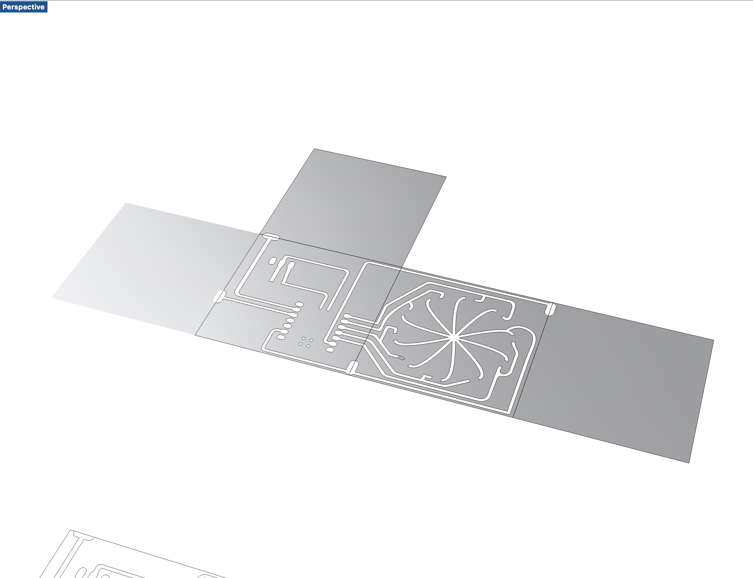
Making surfaces out of the lines

Surfaces connected as a cube
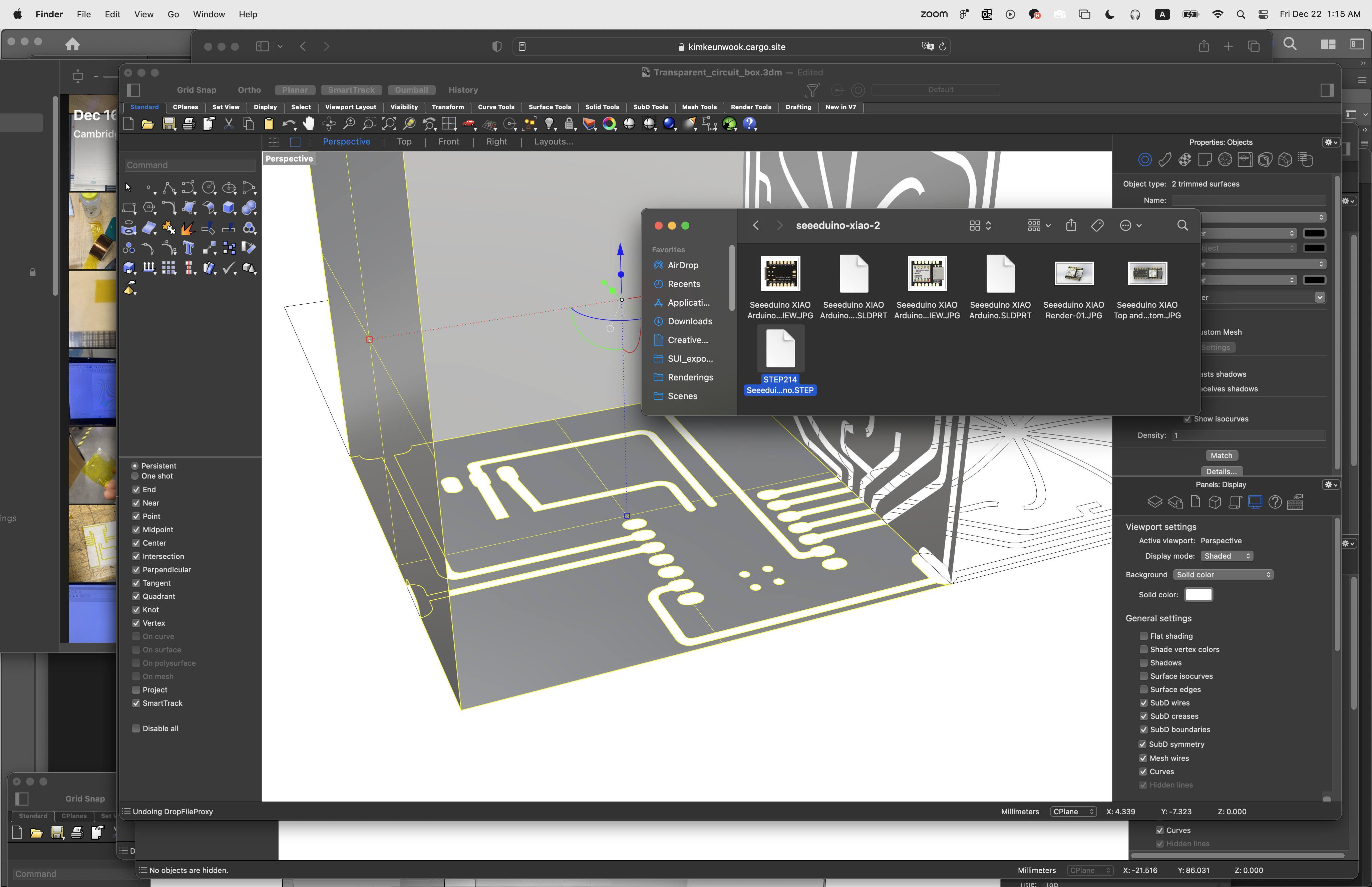
importing Xiao STEP model
 ‘Insert’ the model
Adjust the orientation

Finished 3D layout

Adding battery and switch - all measured with calipers
 Adding LEDs
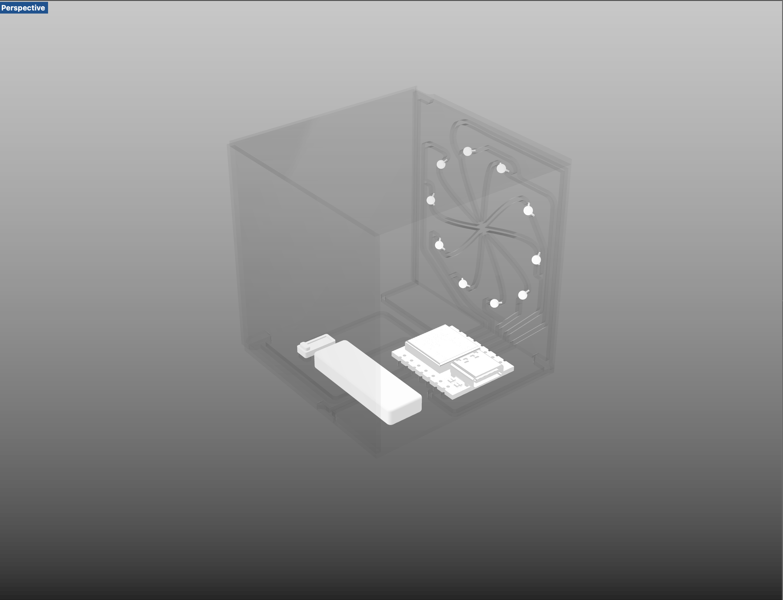

Renders in Rhino are not really recommendable - moving on to Keyshot for a better visualization
[Visualization]
[Outcome]
[Render Process - Keyshot]
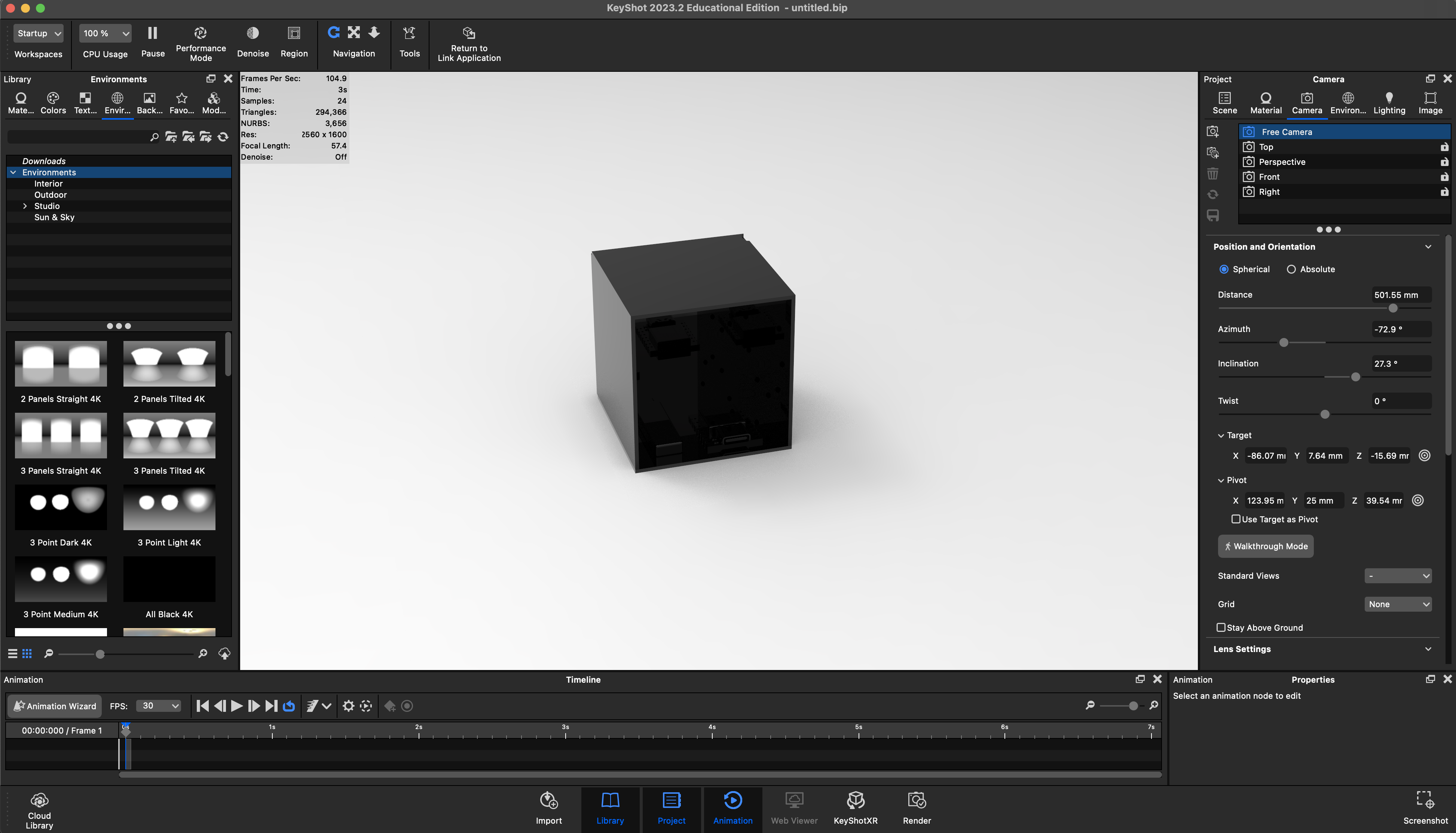
Import the Rhino model directly using Rhino-Keyshot plugin. As the material is not assigned, everything is black or white or other colors based on the rhino render material setting.

Change the material from plastic to glass(solid)

When you import a STEP file or Solidworks file in Rhino, it’s unlikely they are divided into layers by material. The materials should be unliked first to be assigend for right ones.

You can set the right material to the model after several commands such as Ungroup / Explode / assigning material
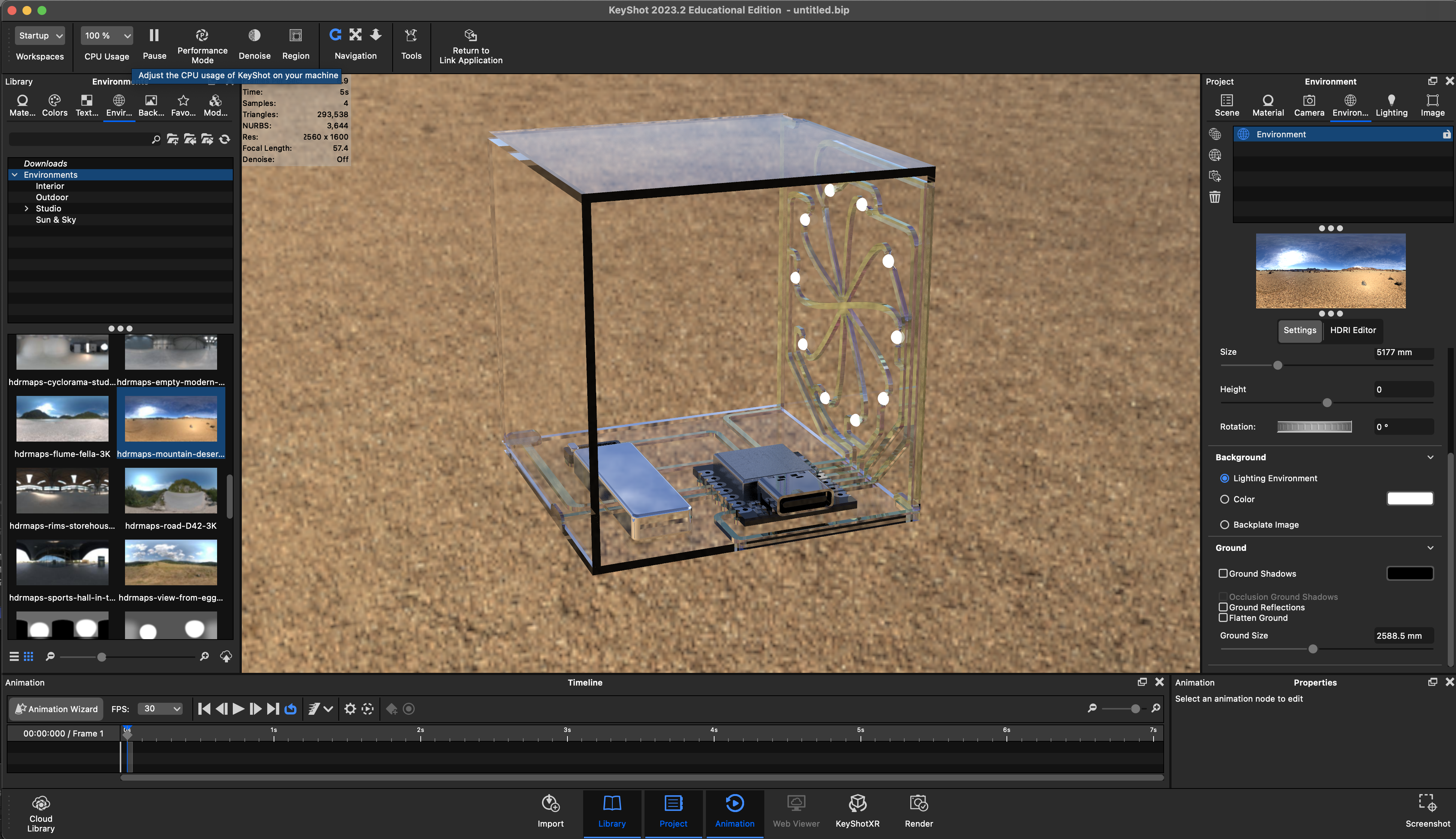
For clear / transparent material, the reflection, texture, and what is behind the object matter.
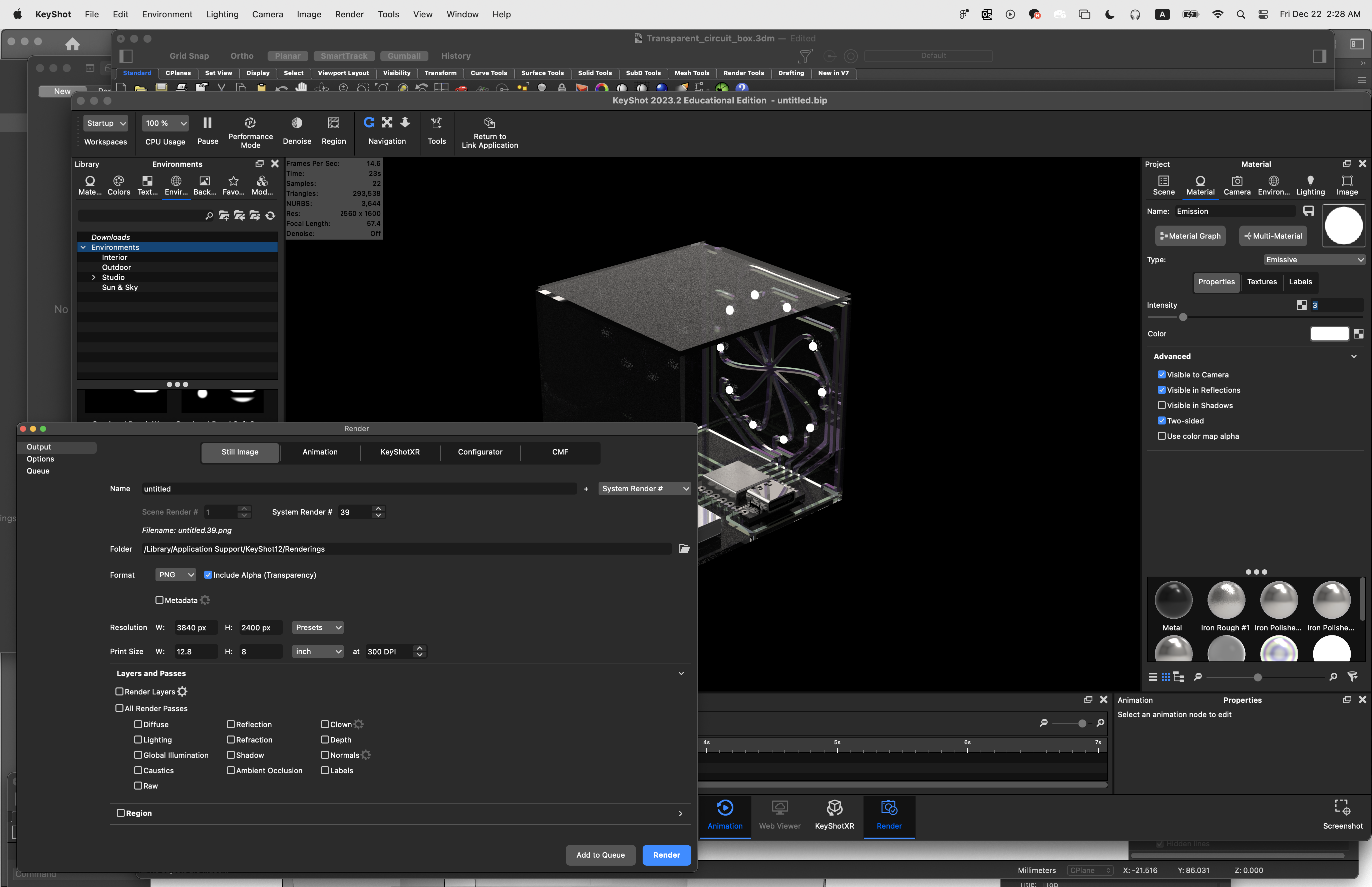
FInally, after assigning lights with emissive and changing the background color, render the final image.
[Process - CAD]
Hundreds of iterations are inevitable to make a working prototype